HRP Hydraulic Rod Pumps
- The original ultra long stroke (up to 336 inces) hydraulic rod pump
- Reduce MTBF and increase efficiencies.
- Eliminates stuffing box leaks.
- Benefits to environment, health & safety.
- Hazardous area safe - no electrical components on wellhead
- Field proven & tested since 1987.

Hydraulic Rod Pumps, Intl. , founded in 1987 in Placentia CA is a world leader in hydraulic rod pumping technology. For over 3 decades, the company had been focusing and developing the world's most durable and advance rod pumping equipment. Their technology & equipment is field proven and had been highly successful in delivering ultra reliable performance for producers worldwide.
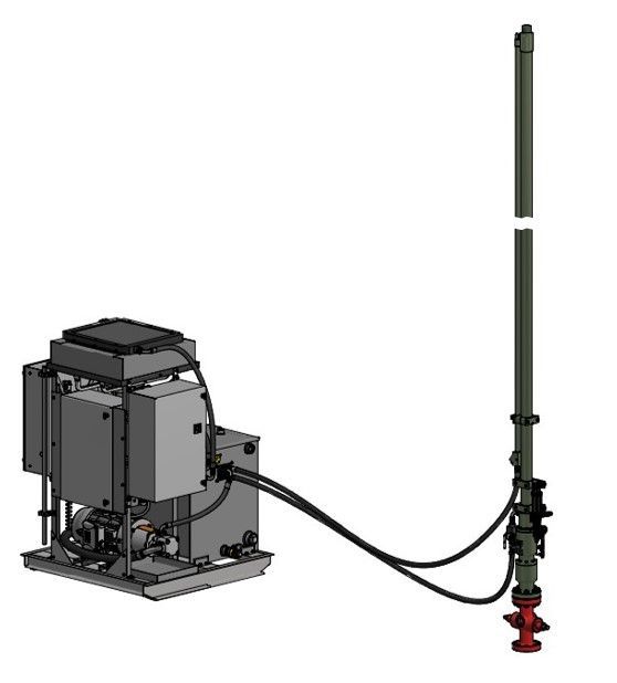
Hydraulic rod pumps provide an alternative to traditional beam units, ESP’s, PCP’s, Gas Lift, etc. combining the reliability and durability of a long stroke rod pump with a minimal wellhead footprint. Hydraulic rod pumps are ideal for well production testing, liquid loaded wells & troublesome wells, and deep or deviated wells, in addition to wells where a traditional rod pumps are considered.
The plug & play package comes with the hydraulic cylinder and a hydraulic power unit, well operation is monitored & controlled remotely. Advance controls include pump-off controller, dyno-cards, remote web-based monitoring & control, fluid level monitoring.
Benefits & Advantages of the HRP Hydraulic Rod Pump
Specifications
36 to 336 inches
up to 53,376 lbs
10 to 150 HP
5000 psig
150 deg C
60, 100, 200 US Gallons
3000 psig
2.5 to 5.0 inches
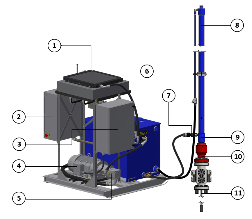
Bill of Materials
| Item | Description |
|---|---|
| 1 | Cooling System |
| 2 | Control Panel with Integrated 3G/Wifi Modem |
| 3 | Advance Pump Controller |
| 4 | Prime Mover |
| 5 | Hydraulic Vane Pump |
| 6 | Hydraulic Reservoir with valving system and sensors |
| 7 | Hydraulic Fluid Intake |
| 8 | Hydraulic Cylinder with Piston |
| 9 | Integrated Sealing System |
| 10 | Wellhead Adapter |
| 11 | Intergated Polished Rod |
Long & Slow is the way to go
Rod pump technology has evolved only slightly in the last three decades with one exception: Long stroke and ultra-long stroke HRP pumping units. The necessity to maximize economical efficiencies of rod-pumped oil and gas wells has created a high demand for longer stroke lengths, as most other elements of the rod-pumped well present little room for improvement. The benefits of long and ultra-long stroke pumping units includes increased production rates, reduced bottomhole equipment wear, decreased rod string fatigue, minimized tubing wear in both vertical and directional wells and lower occurrences of bottomhole pump gas locking. These benefits are discussed below in an overview of applied long stroke and ultra-long stroke pumping technology.
Explore below on the benefits of pumping your well long & slow.
Advance Pump Controller
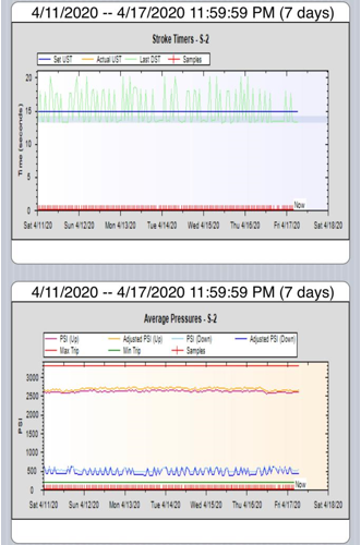
Live & Historical Dynamometer Cards
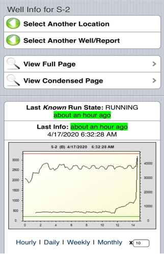
Dynamometer Cards (Dyno Cards) allow the user to understand and analyse the performance of the downhole equipment. HRP's advance controller provide live Dyno Cards locally and remotely.
You can overlay dynos directly in the web browser with no additional software or plugins to install. Notice the time based dynamometer graph resembles a downhole pump dyno card. In some case, our ability to allow rods to fall faster can be utilized to achieve a greater overall SPM than can be obtained with traditional rod pumps.
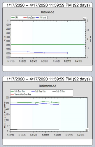
Trend Analysis Graphs
Graphing fluid level, production, and other equipment parameters allows for rapid analysis of conditions affecting current and historical well performance.
Overview reports simplify the process of finding problems or identifying potential candidates for optimization. For example, fluid level decline can be identified before reaching a pumped off condition. The historical strokes per minute and fluid level enable the user to better estimate the optimal SPM to maintain a consistent fluid level.
Likewise, production well test graphs can identify changes in bottom hole conditions and pump efficiencies over time.
Surface equipment data such as polished rod load can be graphed over time to easily indicate changing conditions. Coupled with email and text message alerts, any deviation from historical polished rod load can quickly indicate trouble conditions.
Complete Well History
Fluid levels, production tests, workover history, chemical analysis, rod/tubing diagnostics, surface equipment data, historical comments, and more are all available to the user.
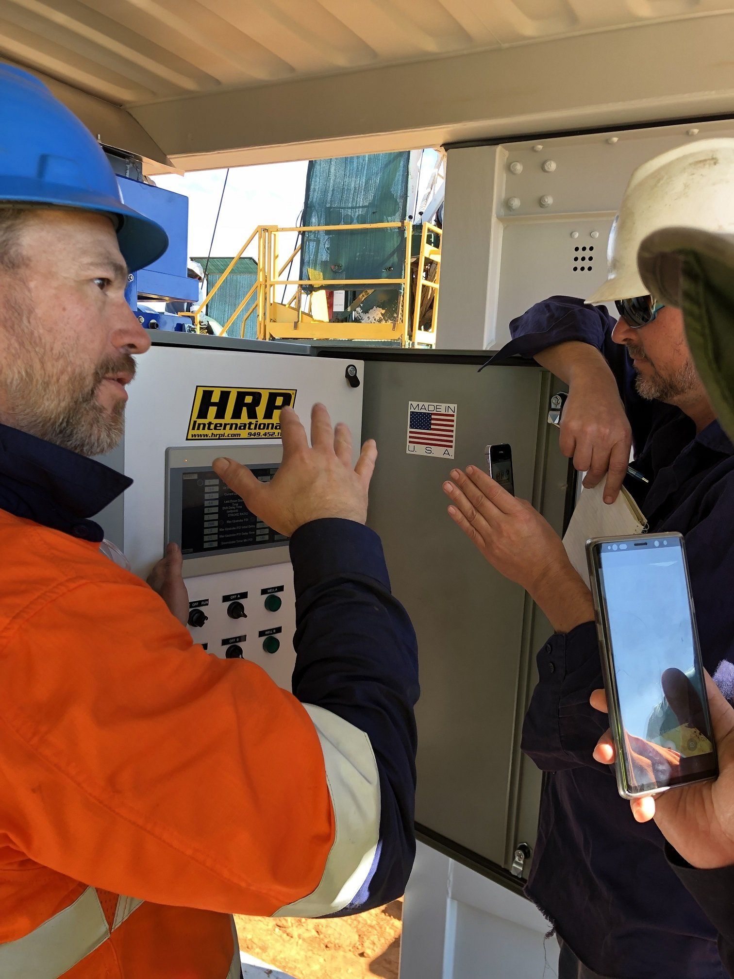
Collaborate Remotely
The web-based interface is ideal for distributing important information to key personnel involved in the design, operation, or maintenance of wells and equipment.
Used in conjunction with teleconferences Operators, Engineers,and Service Providers can collectively troubleshoot or review wells. In addition, well-specific comments are stored on the website to aid in future troubleshooting.

Pump Speed Adjustment
Change speed locally on the intuitive HRP HMI touchscreen on the pump controller or remote via your computer, tablet or phone via a wifi or cellular network.
Speed adjustment is immediate and users will be able to monitor the SPM real time.
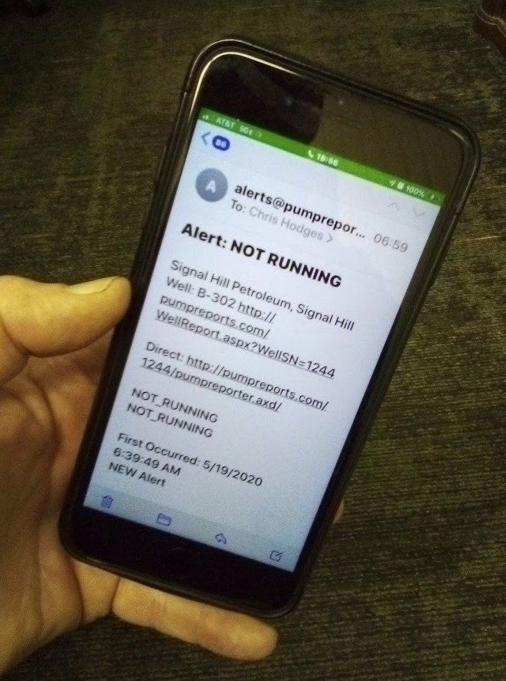
Email & Test Alerts
Customizable alerts provide notification of potential trouble conditions direct to your cell phone. Trouble conditions can then be addressed proactively. Alerts can be delivered as they occur, or can provide summary information.
From these automated alerts, a single person can monitor multiple locations.
Fluid Level vs Pump Speed

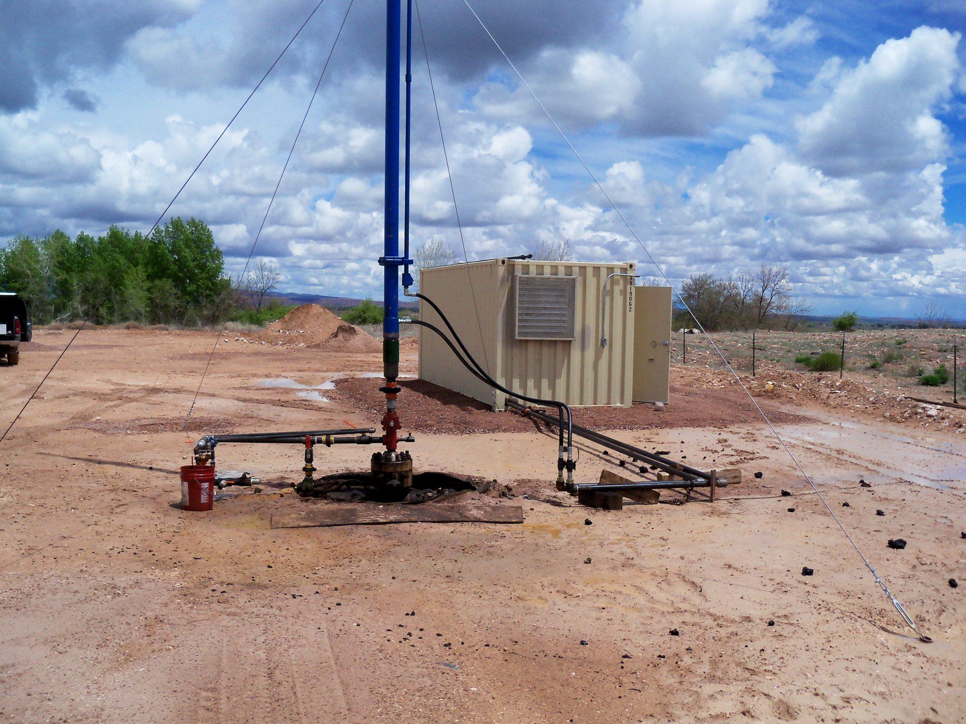
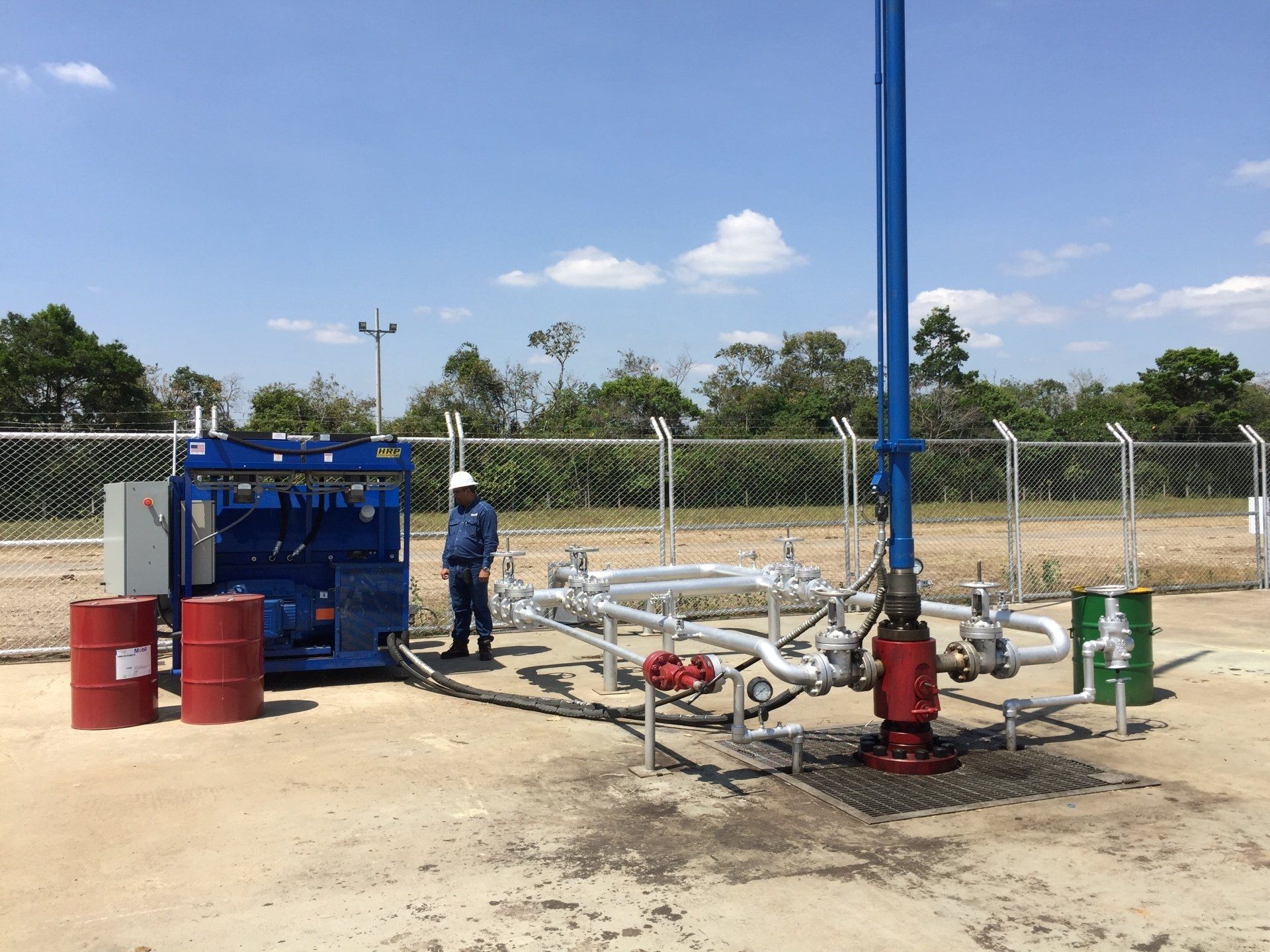
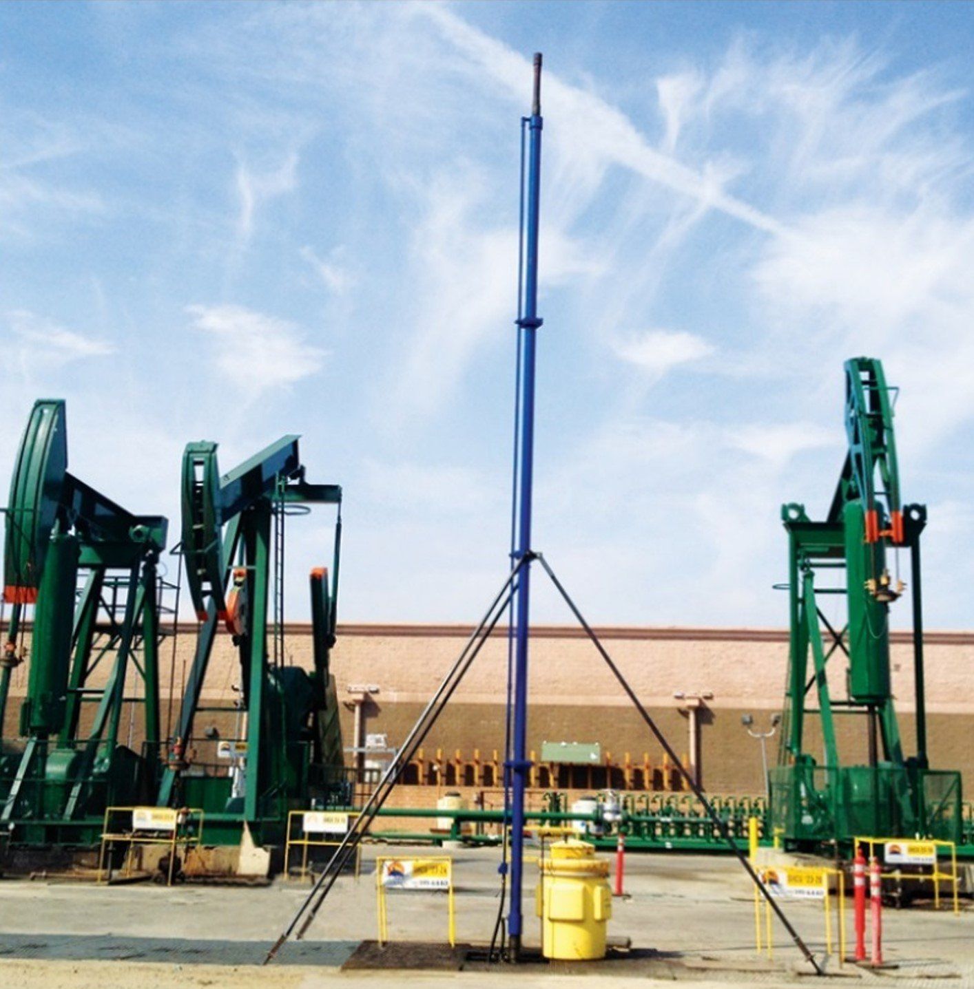
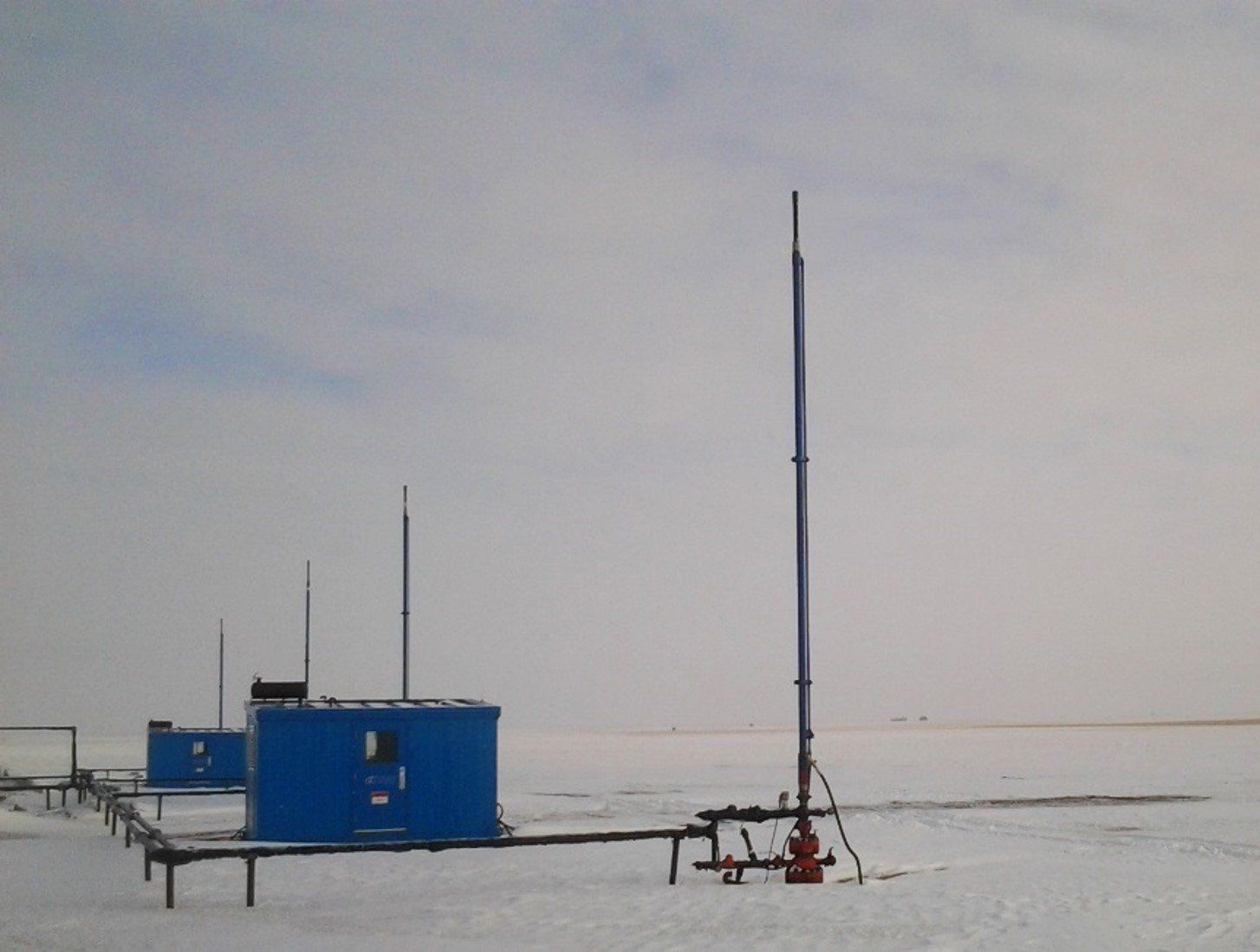
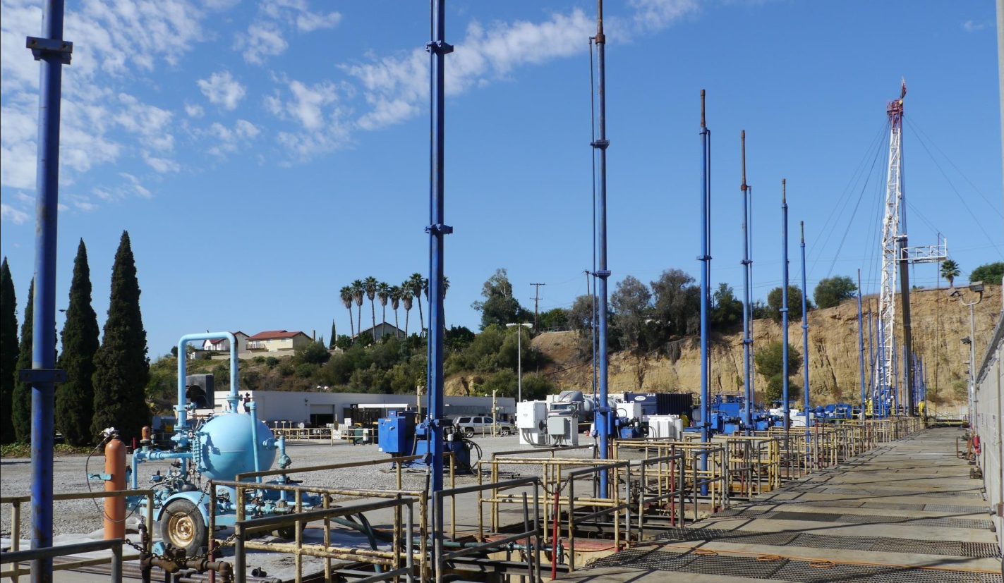
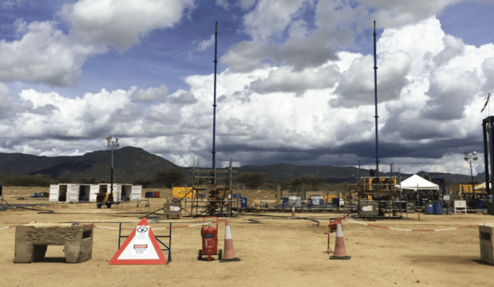
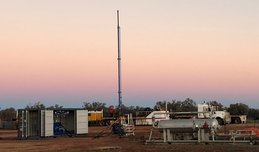
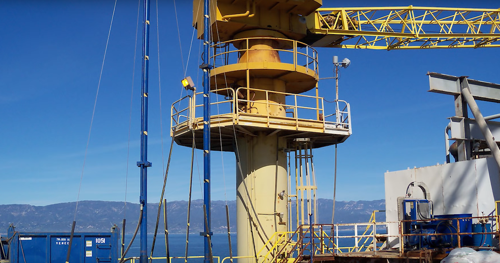
HRP Installation Gallery