Hydraulic Tubing Anchors
Hydraulic Tubing Anchors
- Simple to install, simple to extract
- Sets and unsets automatically
- Strong holding power, maximizes pump efficiency
- No surface manipulation or pretension needed
- Can only move downwards, keep tubing in constant tension
- Large bypass for gas, solids, survey tools
Download Brochure
Black Gold Pump & Supply is proud to be the leading innovator of the Hydraulic Tubing Anchor. Years of research, development and improvements resulted in this revolutionary product being deployed worldwide, replacing conventional mechanical anchors with its many benefits and advantages.
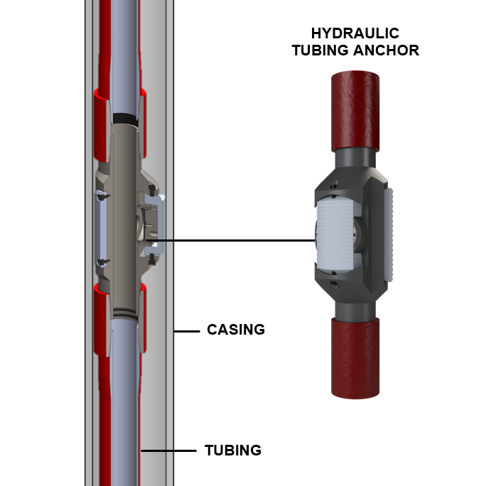
The hydraulic tubing anchor is a completely automatic tool that utilizes the weight of the fluid column in the tubing string to power the piston in the anchor. Load reversal from the pump is the force that moves the hydraulic tubing anchor into tension. When the differential pressure in the tubing string is greater than the pressure in the casing annulus, the anchor piston will be activated hydraulically and press the live slip against the casing.
Only 10 psi of differential pressure is needed to activate the piston. The anchor’s holding power is designed to resist upward movement against the normal forces encountered in the pumping operation, but will yield to forces beyond normal that would over stress the tubing string.
Fixed slips are designed to span recesses, and are built with a proprietary tooth angle, which allows the anchor to move down the hole into proper tension position, but restricts upward movement.
Because they are simple to install and extract, the ease of operation is a strong advantage of hydraulic tubing anchors. Unlike a mechanical anchor, there is no need for surface manipulation to set a hydraulic anchor.
The hydraulic anchor is activated when the insert or tubing pump is set and the pressure in the tubing string is greater than the pressure in the casing annulus. To retrieve the anchor,simply unseat the pump. The pressure will equalize and the anchor will no longer be in tension.
Advantages of the Hydraulic Tubing Anchor
Specifications
| Casing Size Range (inch) | 4.5”, 5”, 5-1/2”, 7”, 7-5/8”, 8-5/8”, 9-5/8” |
|---|---|
| Tubing Size Range (inch) | 2.375, 2.785, 3.50 |
| Minimum Pressure To Set | 10 psi |